Building Services Engineer for Dummies
Table of ContentsThe Ultimate Guide To Building Services EngineerExamine This Report on Building Services EngineerOur Building Services Engineer IdeasEverything about Building Services EngineerA Biased View of Building Services Engineer
Whether you're a student, an educator, or a long-lasting learner, Vocabulary. com can put you on the course to organized vocabulary enhancement.This area is a mainly from the viewpoint of Lagrangian characteristics. In specific, we review the equations of a string as an example of a field theory in one measurement. We start with the like a single particle. Lagrange's equations are where the are the collaborates of the particle.
Similarly, we can specify the where are the momenta conjugate to the coordinates. For a constant system, like a, the Lagrangian is an integral of a Lagrangian density function. For instance, for a string, where is Young's modulus for the product of the string and is the mass density.
The Buzz on Building Services Engineer
For the string, this would be. Remember that the Lagrangian is a function of and its area and time derivatives. The can be calculated from the Lagrangian density and is a function of the coordinate and its conjugate momentum. In this example of a string, is a. The string has a displacement at each point along it which differs as a function of time.
This is the. There are much easier methods to get to this wave equation, but, as we move away from simple mechanical systems, an official method of case will be extremely useful. Jim Branson 2013-04-22.
Mechanical Systems Style & Analysis Engineer Los Angeles, CA Mechanical Systems Design & Analysis Engineer 10/2016 present Los Angeles, CA Mechanical Systems Design & Analysis Engineer 10/2016 present Supports system parts' designs/proposals requirements to provide installation and information documentationTrains othersDetermine and establish methods to solutionsDevelop, document, and maintain processes, approaches, and toolsHelp resolve programmatic and technical issues that would affect expense, schedule, and performanceDevelop and translate drawings, data sets, reports, and specificationsSupports the development, maintenance or adjustment of system, part and installation designs/proposals to provide style documents to downstream groups.
Indicators on Building Services Engineer You Need To Know
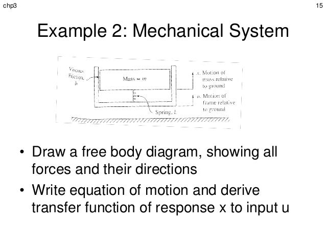
If you are more familiar with mechanical systems, this example may assist strengthen a few of the principles we've covered up until now. The system we want to design is the one displayed in the following figure: It deserves explaining how much easier it is to convey the intent of a model by providing it in schematic form.
While we are currently focusing on formulas and variables, we will eventually work our method up to a technique (in the upcoming section of the book on Parts) where. For now, however, we will focus on how to express the equations associated with this easy mechanical system. Each inertia has a rotational position, varphi, and a rotational speed, omega where omega = dot varphi.
About Building Services Engineer

Pulling all of these variables and equations together, we can express this issue in Modelica as follows: design SecondOrderSystem "A second order rotational system" type Angle= Real( unit=" rad"); type AngularVelocity= Genuine( unit=" rad/s"); type Inertia= Real( unit=" kg. m2"); type Tightness= Genuine( system=" N.m/ rad"); type Damping= Real( system=" N.m. s/rad"); criterion Inertia J1= 0. 4 "Moment of inertia for inertia 1"; parameter Inertia J2= 1. 0 "Moment of inertia for inertia 2"; specification Stiffness c1= 11 "Spring consistent for spring 1"; parameter Stiffness c2= 5 "Spring consistent for spring 2"; criterion Damping d1= 0.
0 "Damping for damper 2"; Angle phi1 "Angle for inertia 1"; Angle phi2 "Angle for inertia 2"; AngularVelocity omega1 "Velocity of inertia 1"; AngularVelocity omega2 "Speed of inertia 2"; see this website initial formula phi1 = 0; phi2 = 1; omega1 = 0; omega2 = 0; formula// Equations for inertia 1 omega1 = der( phi1); J1 * der( omega1) = c1 *( phi2-phi1)+ d1 * der( phi2-phi1);// Formulas for inertia 2 omega2 = der( phi2); J2 index * der( omega2) = c1 *( phi1-phi2)+ d1 * der( phi1-phi2)- c2 * phi2-d2 * der( phi2); end SecondOrderSystem; As we made with the low-pass filter example, RLC1, let's walk through this line by line.
m2"); type Stiffness= Real( unit=" N.m/ rad"); type Damping= Genuine( unit=" N.m. s/rad"); Then we specify the numerous criteria utilized to represent the different physical qualities of our system: specification Inertia J1= 0. 4 "Minute of inertia for inertia 1"; parameter Inertia J2= 1. 0 "Minute of inertia for inertia 2"; specification Tightness c1= 11 "Spring consistent for spring 1"; criterion Tightness c2= 5 "Spring consistent for spring 2"; specification Damping d1= 0.
Fascination About Building Services Engineer
0 "Damping for damper 2"; For this system, there are 4 non-parameter variables. These are defined as follows: Angle phi1 "Angle for inertia 1"; Angle phi2 "Angle for inertia 2"; AngularVelocity omega1 "Velocity of inertia 1"; AngularVelocity omega2 "Speed of inertia 2"; The initial conditions (which we will review shortly) are then defined with: initial equation phi1 = 0; phi2 = 1; omega1 = 0; omega2 = 0; Then come the formulas explaining the dynamic action of our system: equation// Formulas for inertia 1 omega1 = der( phi1); J1 * der( omega1) = c1 *( phi2-phi1)+ d1 * der( phi2-phi1);// Formulas for inertia 2 omega2 = der( phi2); J2 * der( omega2) = c1 *( phi1-phi2)+ d1 * der( phi1-phi2)- c2 * phi2-d2 * der( phi2); And lastly, we have the closing of our design meaning - building services engineer.
This indicates that we will be unable to specify any alternative set of preliminary conditions for this model. We can overcome this problem, as we made with our Newton cooling examples, by specifying specification variables to represent the preliminary conditions as follows: model SecondOrderSystemInitParams "A second order rotational system with initialization parameters" type Angle= Genuine( system=" rad"); type AngularVelocity= Genuine( system=" rad/s"); type Inertia= Genuine( system=" kg - building services engineer.